

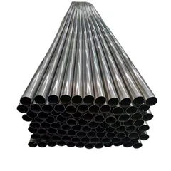


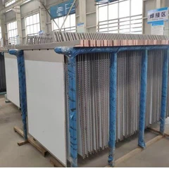


Shell And Tube Heat Exchangers
The heat transfer coefficient is 6000-8000W/m2.0C.
High temperature resistance: (400 ℃),
High pressure resistance: (2.5Mpa)
Heat exchange rate Qh (KW): 140~1350
Heat storage (KW): ≥ 30min Qh
Applicable steam pressure Mpa: 0.2~0.6
Heating water inlet and outlet temperature ℃: 10/60
Heating water cation force MPa: ≤ 0.003
Products Description
A shell and tube heat exchanger is a type of wall heat exchanger that utilizes the tube bundle enclosed within the shell as the heat transfer surface. This heat exchanger has a simple structure, low cost, a wide flow cross-section, and is easy to descale. However, its heat transfer coefficient is relatively low, and it occupies a large floor space. It can be constructed from various metal structural materials, such as stainless steel, titanium, titanium-steel composite materials, and nickel-based materials. It is suitable for high-temperature and high-pressure applications and is the most widely used type of heat exchanger.
The main control parameters of a shell and tube heat exchanger include heating area, hot water flow, heat transfer capacity, and heat medium parameters.
Heat transfer coefficient: 6000-8000 W/m²·°C
High-temperature resistance: up to 400°C
High-pressure resistance: up to 2.5 MPa
Heat exchange rate (Qh): 140–1350 kW
Heat storage: ≥30 min Qh
Applicable steam pressure: 0.2–0.6 MPa
Heating water inlet and outlet temperature: 10°C / 60°C
Heating water cation concentration: ≤0.003 MPa
This revised version corrects grammatical errors while keeping the technical details intact. Let me know if you'd like further refinements!
Because the temperature of the fluid inside and outside the tubes differs, the temperatures of the shell and the tube bundle in the heat exchanger also vary. If the temperature difference is significant, substantial thermal stress will be generated within the heat exchanger, potentially causing the tubes to bend, break, or detach from the tube sheet. Therefore, when the temperature difference between the tube bundle and the shell exceeds 50°C, appropriate compensation measures must be taken to eliminate or reduce thermal stress.
Based on the compensation measures used, shell and tube heat exchangers can be classified into the following main types:
Performance comparison of various types of heat exchangers:
| Compare items | Floating coil heat exchanger | Threaded tube heat exchanger | Eddy current heat film heat exchanger |
| Applicable media types | Steam, water vapor, | Steam, water vapor, | Water Weakly corrosive chemical raw materials, steam, water |
| Parameter range of media Temperature: | Temperature: 0-150 degrees Pressure: 0-1.0MPa |
Temperature: 0-150 degrees Pressure: 0-1.6MPa |
Temperature: -40-400 degrees Pressure: 0-10.0MPa |
| Thermal efficiency | Thermal efficiency = 92% | Thermal efficiency = 93% | Thermal efficiency = 96% |
| Anti-scaling performance | Automatic descaling | Manual descaling | With anti-scaling function |
| Shock resistance, noise | Large vibration, noise | Large vibration, small noise | Small vibration, small noise |
| Service life | About 7 years | About 10 years | About 20 years |
| Shutdown for maintenance | Shutdown for maintenance, replace the tube bundle | Shutdown for maintenance, pull out the tube and expand it | No maintenance required |
Key points for selecting heat exchangers
1. Determine the required heat exchange area based on the known flow rates of the cold and hot fluids, their initial and final temperatures, and their specific heat capacities. To estimate the heat exchange area preliminarily, first assume a heat transfer coefficient, determine the heat exchanger structure, and then verify the heat transfer coefficient (K value).
2. When selecting a heat exchanger, consider the pressure level, operating temperature, and connection conditions of the interface. Under the premise that pressure drop and installation conditions allow, a shell and tube heat exchanger with a smaller diameter and extended structure should be selected, as this helps enhance heat exchange capacity.
3. The pressure drop of the heat exchanger should not be too large and is generally controlled between 0.01 and 0.05 MPa.
4. The flow rate should take into account the viscosity of the fluid. For high-viscosity fluids, the flow rate should be between 0.5 and 1.0 m/s; for general fluids, it should be between 0.4 and 1.0 m/s; and for fluids prone to scaling, the flow rate should be between 0.8 and 1.2 m/s.
5. A filter should be installed before high-temperature water enters the heat exchanger.
6. The combined results of the individual processing and configuration of the heat exchanger in the heat exchange station should meet the total heating load and regulation requirements. To meet the user's heat load regulation requirements, the number of heat exchangers with the same heat transfer coefficient should not be less than 2 and should not exceed 5.
Installation points
1. The heat exchanger should undergo a water pressure test at 1.5 times the maximum working pressure. The steam section should be tested at a pressure not lower than the steam supply pressure plus 0.3 MPa, while the hot water section should not be lower than 0.4 MPa. Under the test pressure, there should be no pressure drop for 10 minutes.
2. Sufficient space should be reserved at the front end of the shell and tube heat exchanger for extracting and removing the tube bundle. The distance between its head and the wall or ceiling should be no less than the length of the heat exchanger, and the clear width of the equipment operation channel should be no less than 0.8 m.
3. The installation height of various valves and instruments should allow for convenient operation and observation.
4. The vertical clearance between the highest point of the upper accessories of the heater (typically referring to the safety valve) and the lowest point of the building structure should meet installation and inspection requirements and should not be less than 0.2 m.
Hot Tags: shell and tube heat exchangers, China shell and tube heat exchangers manufacturers, suppliers, factory, titanium equipment
You Might Also Like


Send Inquiry